We provide tools for mounting thermocouples and resistance thermometer.
Flanges
| Fixed flange | Sliding Flange |
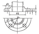 | 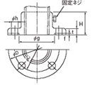 |
unit: mm
| JIS Standards | Size nominal | Models | φD |
Flange dimensions |
Bolt holes |
| A |
B |
SUS304 |
SUS316 |
t |
f |
φg |
H |
φC |
φh |
number |
5kg/cm 2
Flange
Basic dimensions | 10 |
3/8 |
FC3 |
FM3 |
75 |
9 |
1 |
39 |
34 |
55 |
12 |
4 |
| 15 |
1/2 |
FC4 |
FM4 |
80 |
9 |
1 |
44 |
34 |
60 |
12 |
4 |
| 20 |
3/4 |
FC6 |
FM6 |
85 |
10 |
1 |
49 |
35 |
65 |
12 |
4 |
| 25 |
1 |
FC8 |
FM8 |
95 |
10 |
1 |
59 |
35 |
75 |
12 |
4 |
| 40 |
1 1/2 |
FCD |
FMD |
120 |
12 |
2 |
75 |
37 |
95 |
15 |
4 |
| 50 |
2 |
FCE |
FME |
130 |
14 |
2 |
85 |
39 |
105 |
15 |
4 |
| 65 |
2 1/2 |
FCF |
FMF |
155 |
14 |
2 |
110 |
39 |
130 |
15 |
4 |
| 80 |
3 |
FCG |
FMG |
180 |
14 |
2 |
121 |
39 |
145 |
19 |
4 |
| 100 |
4 |
FCH |
FMH |
200 |
16 |
2 |
141 |
41 |
165 |
19 |
8 |
10kg/cm 2
Flange
Basic dimensions |
10 |
3/8 |
JC3 |
JM3 |
90 |
12 |
1 |
46 |
37 |
65 |
15 |
4 |
| 15 |
1/2 |
JC4 |
JM4 |
95 |
12 |
1 |
51 |
37 |
70 |
15 |
4 |
| 20 |
3/4 |
JC6 |
JM6 |
100 |
14 |
1 |
56 |
39 |
75 |
15 |
4 |
| 25 |
1 |
JC8 |
JM8 |
125 |
14 |
1 |
67 |
39 |
90 |
19 |
4 |
| 40 |
1 1/2 |
J.D. |
JMD |
140 |
16 |
2 |
81 |
41 |
105 |
19 |
4 |
| 50 |
2 |
JCE |
J.M.E. |
155 |
16 |
2 |
96 |
41 |
120 |
19 |
4 |
| 65 |
2 1/2 |
JCF |
JMF |
175 |
18 |
2 |
116 |
43 |
140 |
19 |
4 |
| 80 |
3 |
JCG |
JMG |
185 |
18 |
2 |
126 |
43 |
150 |
19 |
8 |
| 100 |
4 |
JCH |
JMH |
210 |
18 |
2 |
151 |
43 |
175 |
19 |
8 |
20kg/cm 2
Flange
Basic dimensions |
25 |
1 |
KC8 |
KM8 |
125 |
16 |
1 |
67 |
41 |
90 |
19 |
4 |
| 40 |
1 1/2 |
K.C.D. |
KMD |
140 |
18 |
2 |
81 |
43 |
105 |
19 |
4 |
| 50 |
2 |
KCE |
KME |
155 |
18 |
2 |
96 |
43 |
120 |
19 |
8 |
| 65 |
2 1/2 |
KCF |
KMF |
175 |
20 |
2 |
116 |
45 |
140 |
23 |
8 |
| 80 |
3 |
KCG |
KMG |
200 |
22 |
2 |
132 |
47 |
160 |
23 |
8 |
| 100 |
4 |
KCH |
KMH |
225 |
24 |
2 |
160 |
49 |
185 |
23 |
8 |
| Chino Standards |
 |
| nominal diameter | Applicable protective pipe diameter
φd | Models |
Flange diameter φD |
Flange dimensions |
Bolt holes |
Mounting bolt |
| Sliding Flange |
Fixed flange |
t |
h |
Center circle diameter φC |
number
n |
Diameter
φE |
| Aluminum |
SUS304 |
SUS316 |
| A | From 17 to 32 | SAA | FCA | FMA |
100 |
10 |
34 |
70 |
4 |
10 |
M8 |
| B |
From 8 to 16 |
SAB |
FCB |
FMB |
70 |
7.5 |
28 |
50 |
4 |
8 |
M6 |
| C |
6.4以下 |
SAC |
FCC |
FMC |
50 |
3 |
13 |
35 |
4 |
4.5 |
M4 |
Nipples
| Straight thread (G) | Tapered thread (R) |
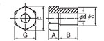 |  |
| (Screw-type sliding nipples have the same dimensions) |
unit: mm
nominal diameter
(B) | Applicable protective pipe diameter
φd | Models | Screw Dimensions | screw
Number of ridges
(25.4
mm)
Attached | Opposite side
and
diagonal | A | B | K |
| Parallel thread |
Tapered Thread |
Outside diameter
C |
Valley Path |
| SUS304 |
SUS316 |
SUS304 |
SUS316 |
G |
F |
| G, R1/8 | 6以下 | SC1 | SM1 | TC1 | TM1 | 9.7 | 8.56 | 28 | 14 |
16.2 |
6 | 10 | 4.0 |
| G, R1/4 |
8以下 |
SC2 |
SM2 |
TC2 |
TM2 |
13.1 |
11.4 |
19 |
17 |
19.6 |
8 |
12 |
6.0 |
| G, R3/8 |
10以下 |
SC3 |
SM3 |
TC3 |
TM3 |
16.6 |
14.9 |
19 |
21 |
24.2 |
10 |
15 |
6.4 |
| G, R1/2 |
12以下 |
SC4 |
SM4 |
TC4 |
TM4 |
20.9 |
18.6 |
14 |
26 |
30 |
12 |
20 |
8.2 |
| G, R3/4 |
16以下 |
SC6 |
SM6 |
TC6 |
TM6 |
26.4 |
24.1 |
14 |
32 |
37 |
16 |
25 |
9.5 |
| G, R1 |
22以下 |
SC8 |
SM8 |
TC8 |
TM8 |
33.2 |
30.2 |
11 |
41 |
47.3 |
20 |
30 |
10.4 |
*When ordering nipples, please designate fixed or sliding and the inner diameter.
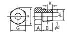
Compression fitting
| Type 1 | Type 2 |
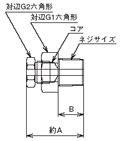 |  |
unit: mm
| Models |
| Copper Core | CF1 | CF2 | CF3 | CF4 | CF6 | CF8 |
| Teflon Core |
CR1 |
CR2 |
CR3 |
CR4 |
CR6 |
CR8 |
| Screw Size |
R1/8 |
R1/4 |
R3/8 |
R1/2 |
R3/4 |
R1 |
| For φ1.0 |
A=35
B=10
G1=14
G2=14 |
A=31
B=12
G1=17
G2=14 |
A=36
B=15
G1=21
G2=14 |
A=43
B=20
G1=26
G2=14 |
A=50
B=18
G1=32
G2=14
G3=17 |
A=52
B=20
G1=38
G2=14
G3=17 |
| For φ1.6 |
| For φ2.0 |
| For φ3.2 |
| For φ4.8 |
| For φ6.0 |
| For φ6.4 |
|
A=39
G2=17 |
G2=17 |
A=43
G2=17 |
A=58
G2=17 |
A=60
G2=17 |
| For φ8.0 |
|
| For φ10 |
|
|
A=41
G2=21 |
A=44
G2=21 |
A=53
B=25
G2=21 |
A=62
B=25
G1=41
G2=21 |
| For φ12 |
|
|
|
A=53
G2=26 |
A=55
G2=26 |
A=63
G2=26 |
| For φ15 |
|
Not available for production |
| For φ16 |
|
|
|
|
A=60
G2=32 |
A=65
G2=32 |
| For φ22 |
|
|
|
|
|
G2=41 |
Compression fitting product number list
*Please refer to the catalog for other specifications.