1. Thin film measurement
When light passes through or reflects off a thin film, the reflections on the front and back surfaces interfere with each other. This is the same phenomenon that makes thin oil films and soap bubbles appear rainbow-colored in our daily lives.
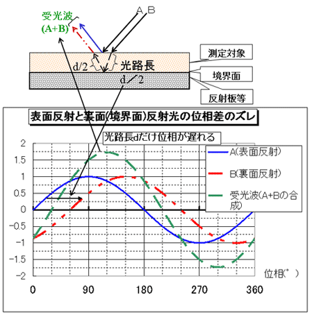
The same is true for infrared rays. In the near-infrared region (0.7 to 3 μm), which is generally in the extremely thin region of 15 μm or less, a phenomenon is observed in which the light reflected from the surface and the back surface (boundary surface) of a film or coating interfere with each other due to the phase difference of the light caused by the difference in optical path length.
*However, interference does not always occur. In cases where the surface is scattering (having fine bumps and grooves), the reflected light is scattered and therefore interference does not occur.
A model diagram of this light interference is shown below.

2. P polarized light
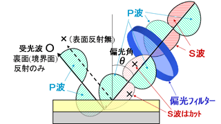
To avoid light interference that occurs when measuring thin films as described in the previous section, the P polarized light method described below is available. This method can cut out surface reflections by placing polarized light filter (
*1) in sight path and extracting and irradiating only the P wave out of the polarized light constituent P wave (longitudinal wave) (
*2) and S wave (transverse wave), thus eliminating light interference.
*1: Light is a type of electromagnetic wave as mentioned above, and electromagnetic waves generate an electric field (magnetic field) due to the flow (change) of electric charge (current). Therefore, we can say that light is vibration in the direction of this flow of charge (current). This vibration direction overlaps with various directions in ordinary light, and the light as a whole is unpolarized. Polarization filter is the extraction of light in one direction from unpolarized light. Polarized light filter consists of microscopically fine slits arranged at equal intervals in the same direction. When light passes through these slits, only light in that direction vibration constituent is transmitted, and polarized light constituent can be extracted.
2: P-wave means parallel polarization and refers to light parallel to the irradiation plane (longitudinal wave in the figure below).

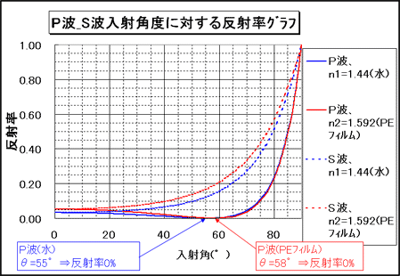
The method for eliminating optical interference makes it possible to eliminate interference by utilizing characteristic of the incident angle and reflectance of this P polarized light light (refer the graph below).

Looking at this diagram, we can see that the reflectivity of P waves is 0% at a certain angle. This angle is called the polarization angle (Brewster angle) and is expressed by the following formula.
Polarization angle θ=tan-1(n/n0)
(n0 = refractive index of air, n = refractive index of the object being measured)
This polarization angle is generally 57 to 58 degrees for polymers, and by projecting light at this angle, there is no surface reflection, making it possible to make measurements without optical interference.
Our ultra-thin thickness gauge (IRMT series) uses this P polarized light method, enabling high accuracy measurement of thin film constituent (thickness, etc.) without being affected by optical interference.


